Air Valves in GVF Solver
An Air Valve is the model element used to represent air relief valves, air release valves, vacuum breaker valves and combination air valves. The underlying behavior of the valves is to be closed when the hydraulic grade is above the valve elevation and to open to maintain atmospheric pressure when the hydraulic grade would otherwise have dropped below the valve.
While they are useful in normal operation of pressure pipes, they are especially important in transient analysis. See the help for air valves in HAMMER. They are also used in filling and draining of pipelines which is best modeled with the implicit or explicit solvers.
While air valves are often placed on pumps to remove air, their primary use is at high points in pressure piping systems which are the first locations which can experience negative pressure in pressurized water systems and are the most likely places where air can accumulate.
In sewer force mains, irrigation systems and raw water transmission systems, pressure can drop when pumps turn off or head loss becomes excessive and they can often be in the open position and pipes can be partly full, immediately downstream of the high point.
Because air valves can change status during a model run, they can introduce instability in the run. The more air valves, the more likely this is to occur. In systems with multiple valves, it is best to focus the analysis on those valves which are likely to open and close. The valves that are almost certain to be closed in the analysis can have a property "Treat as Junction?" set to True and the air valve will behave as a junction node in the model run. The "Treat as Junction" property is the only property in steady and EPS runs that is different between a pressure junction and an air valve. For transient analysis (available in HAMMER), there are numerous other properties that can come into play.
If there is no air valve at a high point and the pressure drops below zero, the pipeline will behave as a siphon. This is generally not recommended as flexible pipes may collapse and corrosive gases can build up in the high point.
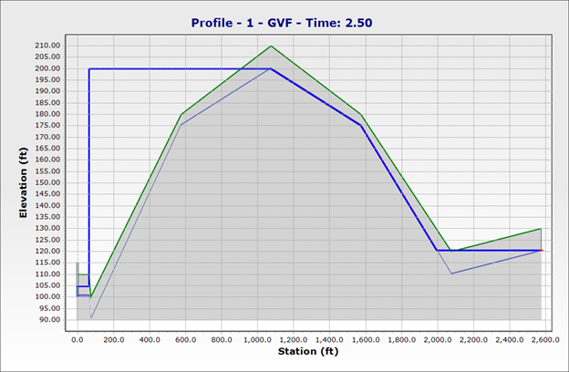
The behavior of air valves can be best viewed using a profile view. With no air valve, the profile of a siphon would look like the figure below with the hydraulic grade below the node level.

With an air valve in place, the valve would prevent the negative pressure by opening to atmosphere. There may be partially full flow downstream of the high point (where the hydraulic grade line coincides with the pipe). The location where the hydraulic grade line rises over the pipe is the location where full pipe flow is restored.

In most cases, when the pump is operating, the hydraulic grade line will remain above the pipe and the air valve will be closed.

When the pump or other source on the upstream side of the high point is shut off or closed, the pipe generally remains full. Therefore, the profile will be flat between the pump and the high point. The GVF solver does not account for the time it takes to fill the downstream section of pipe beyond the air valve once the pump is turned back on based on the assumption that the time to fill the pipe is small compared with the model time step. If analysis of the filling of a pipe is critical, the implicit or explicit solver should be used (available in SewerGEMS or CivilStorm).